Audio Processing and Clock Recovery
Overview
This section explains the requirements for audio marshalling and clock recovery in a typical application using the Sienda TSN stack. It is assumed that the audio interface is being driven by an adjustable clock source and that a timer value capture is triggered by the digital audio frame clock, generating a synchronous interrupt for the system tick. Please see the ‘FSCLK rate/phase measurement’ in the architecture guide for more information on this.
It is also assumed that the reader is familiar with the stack callbacks mechanism, requiring a user-implemented StackCallbacks.cpp. Please see ‘Callback Functions’ in the programming guide for more information.
Audio Buffers
In order to implement audio input and output functionality, the stack must be provided with two audio buffers by the application:
The ‘listener output’ buffer where the stack stores audio samples received from the network as a listener.
The ‘talker input’ buffer where the application stores captured or generated audio data ready for transmission over the network as a talker.
These buffers are passed to the stack through the appGetAudioBuffers callback, implemented by the user which is called after stack initialisation. Example code is given below:
In the user-defined StackCallbacks.cpp:
extern SampleT audioInputBuffers[N_IN_CHANNELS][N_BUFF_SAMPS];
extern SampleT audioOutputBuffers[N_OUT_CHANNELS][N_BUFF_SAMPS];
...

void appGetAudioBuffers(uint32_t* pTalkerInputBuffersNumberOfChannels,
                        SampleT*** pTalkerInputBuffers,
                        uint32_t* pTalkerInputBuffersNumberOfFrames,
                        uint32_t* pListenerOutputBuffersNumberOfChannels,
                        SampleT*** plistenerOutputBuffers,
                        uint32_t* pListenerOutputBuffersNumberOfFrames)
{
    *pTalkerInputBuffersNumberOfChannels = N_IN_CHANNELS;
    *pTalkerInputBuffers = audioInputBuffers;
    *pTalkerInputBuffersNumberOfFrames = N_BUFF_SAMPS;
    *pListenerOutputBuffersNumberOfChannels = N_OUT_CHANNELS;
    *plistenerOutputBuffers = audioOutputBuffers
    *pListenerOutputBuffersNumberOfFrames = N_BUFF_SAMPS;
}
The audio buffer size per channel should be (MAX_SAMPLE_RATE * BUFF_LENGTH_SECONDS). For Milan compliance a listener device must be able to buffer 2.126ms of audio. A 48kHz 2.126ms second buffer would be 103 samples long. It may be useful to round up the buffer size to a multiple of the audio DMA buffer size, or to add additional buffering if the device should support more than the required 2.126ms.
System Tick
It is generally recommended to drive the system from the digital audio frame clock edge because this allows the entire system to be synchronised with the AVB network clock and makes it easy to synchronously update audio sample buffers.
A typical embedded application will implement an 8kHz system tick and perform all of it’s required tasks in this interval. The actions required to for audio processing and clock recovery are listed below and explained in the following ‘Audio Task’ section.
- Increment the ‘system time’ by the measured interval time
- Marshall audio between sample buffers and the digital audio interface
- Update the TSN stack with
setPlayHeadPositionandtxOpportunity
!!! info To reduce the effects of interrupt latency it may be preferable to implement a system tick at some multiple of 8kHz and process several packets of audio at once. In that case this guide still applies, but the process is repeated for each 125us interal.
Audio Task
System Time
As described in the architecture guide, the system should capture a timer value on the digital audio FS clock edge. At each 125us interval, the delta between these catured timer values can be used to increment a system time variable. This keeps an accurate time according to our audio stream which can be used for the neccessary functions below.(setPlayHeadPosition and txOpportunity).
Marshalling samples
This refers to the copying of and re-ordering of samples between the audio buffers used by the stack, and the buffers used by the audio interface.
On each interval of a typical aplication with a 48kHz sample rate, 6 samples from each channel of the audio input would need to be copied to the talker input buffer, and 6 samples from each channel of the listener output buffer would need to be copied to the audio output interface.
Marshalling can be implemented using DMA or any other desired mechanism.
Talker stream
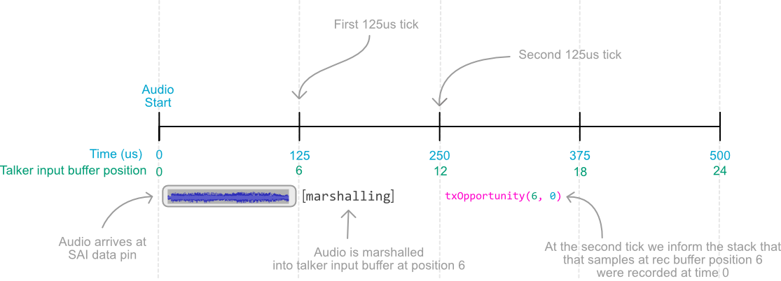
The diagram below shows the order of operations for a block of 6 samples at 48kHz, and the values passed into the txOpportunity(streamPosition, timeAtCapture) stack function. This function essentially tells the stack: ‘There is a 125us interval’s worth of samples available to be sent over the network at this buffer position that were recorded at time x’. The stack will know how many samples are available from the current sample rate.

Listener stream
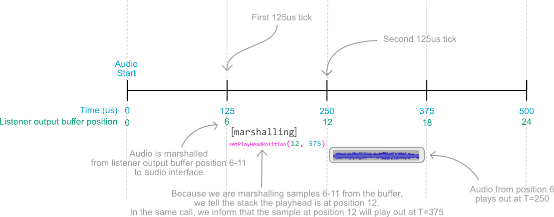
The diagram below shows the order of operations for playing a block of 6 samples out of the mix buffer @48kHz. Calling setPlayHeadPosition(streamPosition, presentationTime) performs 2 functions. Firstly, it updates the clock recovery with the presentation time for a specific stream position, providing a reference point for adjustment. Secondly, it informs the stack of which samples are being ‘played’, and therefore where it is safe to write into the listener output buffer. In the example below, the stack will know that if it receives a packet whose timestamp suggests that it should be written into a position earlier than 12, the stack will discard it because it is too late, and report that the timestamp received was too early.

Clock recovery
To enable clock recovery, the application must implement the void appAdjustClockRate(double ratio, void *pContext) function as declared in StackCallbacks.h.
The stack will automatically call this function when it needs to make an adjustment to the audio clock rate. The ratio value given is simply a ratio of the measured local rate and the desired clock source rate, and can be used as a multiplier.
An example implementation might look like below, where a timer reload value is adjusted by the provided ratio:
void appAdjustClockRate(double ratio, void *pContext)
{
	double timerReloadValue = RELOAD_DEFAULT_FLOAT / ratio;
    setTimerReloadValue(timerReloadValue);
}
!!! info Depending on the system hardware and peripherals, it may be important to keep track of the rounding error or decimal part of the calculation when using the ratio value for best performance.